Chapter 07 · Using RAID and LVM Disk Array Technologies
Chapter Overview
Following Chapter 6's coverage of disk device partitioning, formatting, and mounting, this chapter delves into the characteristics of common RAID (Redundant Array of Independent Disks) solutions.Through practical deployments of RAID 10 and RAID 5 with backup disks, we will demonstrate RAID's powerful capabilities to meet production environment demands for disk I/O throughput and data redundancy backup. Additionally, considering users may dynamically adjust storage resources, this chapter covers LVM (Logical Volume Manager) deployment, expansion, contraction, snapshots, as well as unmounting and deletion procedures.Upon completing this chapter, readers will be equipped to flexibly apply RAID and LVM in enterprise-level production environments to meet advanced storage resource management requirements.
7.1 RAID
For an extended period, CPU processing power has experienced rapid growth. In 2024, Intel released the Core i9-14900KS processor, enabling home computers to achieve 24 cores and 32 threads with a maximum big-core frequency of 6.2GHz.Earlier, AMD introduced the Threadripper 7980X processor, enabling home computers to effortlessly harness the power of 64-core, 128-thread processing beasts.However, disk device performance improvements have been relatively modest, gradually becoming a bottleneck for overall contemporary computer performance. Moreover, due to the need for continuous, frequent, and extensive I/O operations, disk devices experience significantly higher failure rates compared to other components, increasing the risk of critical data loss.
Disk devices rank among the most failure-prone components in computers. Compounded by their critical role in data storage, they cannot be simply replaced like CPUs, memory modules, power supplies, or even motherboards when they fail. Therefore, proactive measures—such as implementing data redundancy and off-site backups—are essential in production environments.
In 1988, the University of California, Berkeley first proposed and defined the concept of RAID technology. RAID technology combines multiple disk devices into a larger, more secure disk array. It divides data into segments and stores them across different physical disks. By utilizing distributed read/write techniques, it enhances the overall performance of the disk array. Simultaneously, through various redundancy strategies, critical data is distributed across multiple physical disks in different ways, achieving redundant data backup.
Every coin has two sides. While RAID technology offers exceptional data redundancy backup capabilities, it correspondingly increases cost expenditures. It's akin to having only one phone book but creating a duplicate copy of contact numbers to prevent loss—necessitating the purchase of an additional phone book and thereby increasing expenses.RAID technology was developed to enhance data reliability, availability, and storage performance. Compared to the value of the data itself, modern enterprises place greater emphasis on the redundant backup mechanism provided by RAID and the resulting improvement in disk throughput. In other words, RAID not only reduces the probability of data loss due to disk device failure but also increases the read/write speed of disk devices. Consequently, it has been widely deployed and applied in the vast majority of operators and large to medium-sized enterprises.
Considering cost and technical factors, it is necessary to balance data reliability and read/write performance based on different requirements, formulating tailored solutions to meet specific needs.Currently, there are at least a dozen existing RAID disk array solutions. Instructor Liu Chuan will now provide a detailed explanation of the four most common solutions: RAID 0, RAID 1, RAID 5, and RAID 10. Table 7-1 compares these four solutions, where n represents the total number of disks.
Table 7-1 Comparison of RAID 0, 1, 5, and 10 Solutions
| RAID Level | Minimum Disks | Available Capacity | Read/Write Performance | Security | Features |
|---|---|---|---|---|---|
| 0 | 2 | n | n | Low | Pursuing maximum capacity and speed, any disk failure will result in complete data loss. |
| 1 | 2 | n/2 | n | High | Pursuing maximum security, data remains unaffected as long as at least one disk in the array group is available. |
| 5 | 3 | n-1 | n-1 | Medium | Under the premise of controlling costs, pursue maximum disk capacity, speed, and security, allowing for one disk failure without affecting data integrity. |
| 10 | 4 | n/2 | n/2 | High | Combining the advantages of RAID 1 and RAID 0, this configuration prioritizes disk speed and data security. It allows for up to half of the disks to fail (provided failures do not occur within the same array) without compromising data integrity. |
1. RAID 0 RAID 0 technology connects multiple physical disk devices (at least two) in series via hardware or software to form a large volume group, writing data sequentially to each physical disk. Under ideal conditions, this can multiply disk read/write performance several times over. However, failure of any single disk will result in complete data loss across the entire system.In layman's terms, RAID 0 effectively boosts disk data throughput but lacks data backup and error recovery capabilities. As shown in Figure 7-1, data is written to separate disk devices—specifically, Disk A and Disk B each store data—ultimately achieving faster read and write speeds.
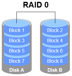
Figure 7-1 RAID 0 Technology Diagram
2. RAID 1
Although RAID 0 technology boosts disk device read/write speeds, it writes data sequentially to each physical disk. This means data is stored separately, and failure of any single disk will corrupt the entire system's data. Therefore, when production environments prioritize data security over disk device read/write speeds, RAID 1 technology becomes necessary.
As illustrated in Figure 7-2, RAID 1 binds two or more disk devices. During data writes, information is simultaneously written to multiple disks (functioning as data mirroring or backup). Should any disk fail, the system automatically restores normal data access by "automatically substituting redundant mirrored data."
Considering the overhead incurred by disk switching during write operations, RAID 1's throughput is marginally lower than RAID 0. However, during data reads, the operating system can retrieve information from both disks simultaneously, theoretically achieving peak read speeds proportional to the number of disks. Furthermore, as long as at least one disk remains operational, data integrity is maintained, ensuring high reliability.
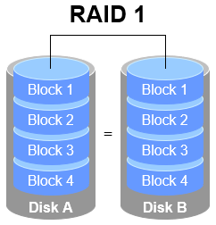
Figure 7-2 RAID 1 Technology Schematic
While RAID 1 prioritizes data security, writing identical data across multiple disks reduces disk utilization.Theoretically, the actual usable disk space shown in Figure 7-2 is only 50%. For a RAID 1 array with three disk devices, the usable rate is approximately 33%, and so on. Furthermore, since data must be written simultaneously to two or more disk devices, this inevitably increases the computational load on the system to some extent.
Is there a RAID solution that balances disk read/write speeds, data security, and cost? In reality, focusing solely on data security and cost makes it impossible to significantly enhance data security while maintaining the original disk utilization rate without adding new hardware.Instructor Liu Chuan has no reason to mislead readers. While the RAID 5 technology discussed below theoretically balances all three factors (read/write speed, data security, and cost), it actually represents a "trade-off" between them.
3. RAID 5
As shown in Figure 7-3, RAID 5 technology stores the parity information of disk device data across other disk devices. Within a RAID 5 array, this parity data is not stored on a single disk but distributed across every other disk device except the one containing the original data. This design ensures that the failure of any single device does not result in a catastrophic loss.The "Parity" section in Figure 7-3 stores this data parity information. In other words, RAID 5 does not actually back up the real data on the disks. Instead, it attempts to reconstruct damaged data using the parity information when a disk device fails. This technical characteristic of RAID represents a "trade-off" that balances disk read/write speeds, data security, and storage costs.
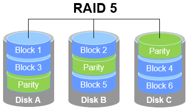
Figure 7-3 RAID 5 Technology Schematic
RAID 5 requires a minimum of three disks and employs disk striping technology. Compared to RAID 1, its advantage lies in storing parity information rather than identical file content. Consequently, when rewriting a file, a RAID 5 array only needs to reference the corresponding parity information, resulting in higher efficiency and reduced storage costs.
4. RAID 10
RAID 5 technology represents a compromise between read/write speed and data security due to disk device cost considerations. However, most enterprises prioritize the value of the data itself over disk prices, making RAID 10 the primary choice for production environments.
As the name implies, RAID 10 is a combination of RAID 1 and RAID 0 technologies.As shown in Figure 7-4, RAID 10 requires at least four disks. First, each pair of disks forms a RAID 1 array to ensure data security. Then, these two RAID 1 arrays are combined using RAID 0 technology to further enhance disk read/write speeds.Theoretically, as long as not all disks within the same array fail, up to 50% of disk devices can be damaged without data loss. Since RAID 10 inherits the high read/write speeds of RAID 0 and the data security of RAID 1, its performance surpasses RAID 5 when cost is disregarded. Consequently, it has become a widely adopted storage technology.
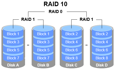
Figure 7-4 RAID 10 Technology Schematic
Tips:
Since RAID 10 is composed of RAID 1 and RAID 0, the correct pronunciation is "RAID one-zero," not "RAID ten."
Careful examination of Figure 7-4 reveals that RAID 10 first divides data into segments before mirroring them in pairs. This means RAID 1 forms the base level, and RAID 0 then combines these RAID 1 disk arrays into a single "block" of storage.RAID 01 operates in the opposite manner: disks are first divided into two groups, then RAID 0 is used as the lowest-level combination. Finally, these two RAID 0 disk groups are combined using RAID 1 technology.
The difference between RAID 10 and RAID 01 is very clear. In RAID 10, the failure of any single disk does not compromise data integrity, as the remaining disks continue functioning normally. In RAID 01, however, the failure of any single disk immediately causes the underlying RAID 0 array to fail, potentially creating serious risks. Consequently, RAID 10 is far more common than RAID 01, and many motherboards do not even support RAID 01.
7.1.1 Deploying Disk Arrays
With the disk device management foundation established in Chapter 6, deploying RAID and LVM becomes straightforward. First, add four disk devices to the virtual machine to create a RAID 10 array, as shown in Figure 7-5.The steps for adding disks are not detailed here; you can perform them yourself. Remember to use disks with SCSI or SATA interface types, and the default size of 20GB is sufficient.
These disk devices are virtualized; there is no need to purchase physical disks and install them in your computer. It is crucial to remember to shut down the system before adding disk devices to the virtual machine. Otherwise, differences in computer architecture may prevent the virtual machine system from recognizing the newly added disk devices.

Figure 7-5 Adding Four Hard Disk Devices
In current production environments, servers typically come equipped with RAID array cards. Although server prices continue to decrease, there is no need to purchase a dedicated server solely for experimentation. Instead, learn to use the mdadm command to create and manage software RAID disk arrays within Linux systems. The theoretical knowledge and operational processes involved are identical to those in production environments.
The mdadm command is used to create, adjust, monitor, and manage software RAID devices. Its name comes from "multiple devices admin," and its basic syntax is mdadm [parameters] device_name.
Common parameters and their functions for the mdadm command are shown in Table 7-2.
Table 7-2 Common Parameters and Functions of the mdadm Command
| Parameter | Function |
|---|---|
| -a | Automatically detect device names |
| -n | Specify the number of devices |
| -l | Specify the RAID level |
| -C | Create a new RAID array |
| -v | Display detailed creation process information |
| -f | Simulate device failure |
| -r | Remove a device |
| -Q | View summary information |
| -D | View detailed information |
| -S | Stop the RAID disk array |
Next, use the mdadm command to create a RAID 10 array named /dev/md0.
As covered in Chapter 6, udev is the service within the Linux kernel responsible for naming hardware. Its naming conventions are straightforward. Based on these rules, we can infer that the second SCSI storage device will be named /dev/sdb, and so on.Deploying a RAID array with disk devices is akin to forming a class with several students, but you wouldn't name the class /dev/sdbcde. While this might reveal its components at a glance, it's hard to remember and read. What if you deploy a RAID array with 10, 50, or 100 disks?
In VMware Workstation 17, the system disk may be incorrectly recognized after restarting the virtual machine, leading to confusing disk naming. Ensure that /dev/sdb, /dev/sdc, /dev/sdd, and /dev/sde are the newly added disks (verify using the command below) to complete the experiment successfully. If /dev/sda is not the primary system disk, restart the virtual machine system.
root@linuxprobe:~# ls -l /dev/sd*
brw-rw----. 1 root disk 8,  0 Mar 17 21:15 /dev/sda
brw-rw----. 1 root disk 8,  1 Mar 17 21:15 /dev/sda1
brw-rw----. 1 root disk 8,  2 Mar 17 21:15 /dev/sda2
brw-rw----. 1 root disk 8,  3 Mar 17 21:15 /dev/sda3
brw-rw----. 1 root disk 8, 16 Mar 17 21:15 /dev/sdb
brw-rw----. 1 root disk 8, 32 Mar 17 21:15 /dev/sdc
brw-rw----. 1 root disk 8, 48 Mar 17 21:15 /dev/sdd
brw-rw----. 1 root disk 8, 64 Mar 17 21:15 /dev/sde
At this point, parameters from mdadm are required. Specifically:The -v parameter displays the creation process. Append a device name like /dev/md0 afterward, so /dev/md0 becomes the name of the created RAID disk array. The -n 4 parameter specifies using 4 disks to deploy this RAID disk array, while the -l 10 parameter indicates a RAID 10 configuration. Finally, add the names of the 4 disk devices to complete the setup.
root@linuxprobe:~# mdadm -Cv /dev/md0 -n 4 -l 10 /dev/sdb /dev/sdc /dev/sdd /dev/sde
mdadm: layout defaults to n2
mdadm: layout defaults to n2
mdadm: chunk size defaults to 512K
mdadm: size set to 20954112K
mdadm: Defaulting to version 1.2 metadata
mdadm: array /dev/md0 started.
The initialization process takes approximately 1 minute. You can monitor progress using the -D parameter. Alternatively, use the -Q parameter for a brief status update:
root@linuxprobe:~# mdadm -Q /dev/md0
/dev/md0: 39.97GiB raid10 4 devices, 0 spares. Use mdadm --detail for more detail.
Students may wonder: why does a disk array group composed of four 20GB disks only offer 39.97GB of usable space?
This brings us to the principle behind RAID 10 technology. It employs RAID 1 arrays in pairs to ensure data reliability, with each piece of data stored twice. This results in a 50% utilization rate and 50% redundancy rate for the disks. Consequently, the total capacity of 80GB is effectively halved.
After waiting two to three minutes, format the newly created RAID array as Ext4:
root@linuxprobe:~# mkfs.ext4 /dev/md0
mke2fs 1.47.1 (20-May-2024)
Creating filesystem with 10477056 4k blocks and 2621440 inodes
Filesystem UUID: 3bec5133-ecb1-4102-a10e-5c22208a76a1
Superblock backups stored on blocks:
	32768, 98304, 163840, 229376, 294912, 819200, 884736, 1605632, 2654208,
	4096000, 7962624

Allocating group tables: done
Writing inode tables: done
Creating journal (65536 blocks): done
Writing superblocks and filesystem accounting information: done
Next, create a mount point and mount the disk device:
root@linuxprobe:~# mkdir /RAID
root@linuxprobe:~# mount /dev/md0 /RAID
root@linuxprobe:~# df -h
Filesystem             Size  Used Avail Use% Mounted on
/dev/mapper/rhel-root   17G  3.7G   13G  23% /
devtmpfs               4.0M     0  4.0M   0% /dev
tmpfs                  1.9G   84K  1.9G   1% /dev/shm
efivarfs               256K   56K  196K  23% /sys/firmware/efi/efivars
tmpfs                  776M  9.7M  767M   2% /run
tmpfs                  1.0M     0  1.0M   0% /run/credentials/systemd-journald.service
/dev/sr0               6.5G  6.5G     0 100% /media/cdrom
/dev/sda2              960M  272M  689M  29% /boot
/dev/sda1              599M  8.3M  591M   2% /boot/efi
tmpfs                  388M  128K  388M   1% /run/user/0
/dev/md0                40G   24K   38G   1% /RAID
Next, examine the detailed information of the /dev/md0 disk array device to verify that the RAID level, array size, and total number of disks are all correct:
root@linuxprobe:~# mdadm -D /dev/md0
/dev/md0:
           Version : 1.2
     Creation Time : Mon Mar 17 21:56:00 2025
        Raid Level : raid10
        Array Size : 41908224 (39.97 GiB 42.91 GB)
     Used Dev Size : 20954112 (19.98 GiB 21.46 GB)
      Raid Devices : 4
     Total Devices : 4
       Persistence : Superblock is persistent

       Update Time : Mon Mar 17 22:02:18 2025
             State : clean
    Active Devices : 4
   Working Devices : 4
    Failed Devices : 0
     Spare Devices : 0

            Layout : near=2
        Chunk Size : 512K

Consistency Policy : resync

              Name : linuxprobe.com:0  (local to host linuxprobe.com)
              UUID : 568d1322:33f4dd42:78d1f692:5ded8f34
            Events : 17

    Number   Major   Minor   RaidDevice State
       0       8       16        0      active sync set-A   /dev/sdb
       1       8       32        1      active sync set-B   /dev/sdc
       2       8       48        2      active sync set-A   /dev/sdd
       3       8       64        3      active sync set-B   /dev/sde
To ensure the created RAID disk array remains operational and isn't deactivated after each reboot, remember to add the information to the /etc/fstab file. This guarantees the RAID disk array remains active after every system restart.
root@linuxprobe:~# echo "/dev/md0 /RAID ext4 defaults 0 0" >> /etc/fstab
root@linuxprobe:~# cat /etc/fstab
#
# /etc/fstab
# Created by anaconda on Wed Mar 12 19:35:26 2025
#
# Accessible filesystems, by reference, are maintained under '/dev/disk/'.
# See man pages fstab(5), findfs(8), mount(8) and/or blkid(8) for more info.
#
# After editing this file, run 'systemctl daemon-reload' to update systemd
# units generated from this file.
#
UUID=408f4a3d-a4d3-4a44-bb23-6988cdbd10bf /                       xfs     defaults        0 0
UUID=4cf8ecae-bcb6-4b1e-8001-968b33643a8a /boot                   xfs     defaults        0 0
UUID=1FB8-9199         			 		  /boot/efi               vfat    umask=0077,shortname=winnt 0 2
UUID=d936c726-45a7-4ca2-8932-c54f84a3d787 none                    swap    defaults        0 0
/dev/cdrom 								  /media/cdrom 			  iso9660 defaults 		  0 0
/dev/md0 								  /RAID 				  ext4 	  defaults 		  0 0
7.1.2 Damaged Disk Array and Repair
The primary reason for deploying RAID 10 disk arrays in production environments is to enhance storage device I/O rates and data security. However, since our disk devices are emulated within virtual machines, improvements in I/O rates may not be immediately apparent. Below, we will explain how to handle a damaged RAID disk array to ensure you remain composed when encountering such issues in your future operations roles.
Upon confirming that a physical disk device is damaged and no longer functional, use the mdadm command to remove it. Then check the RAID array status. You will observe the status has changed:
root@linuxprobe:~# mdadm /dev/md0 -f /dev/sdb
mdadm: set /dev/sdb faulty in /dev/md0
root@linuxprobe:~# mdadm -D /dev/md0
/dev/md0:
           Version : 1.2
     Creation Time : Mon Mar 17 21:56:00 2025
        Raid Level : raid10
        Array Size : 41908224 (39.97 GiB 42.91 GB)
     Used Dev Size : 20954112 (19.98 GiB 21.46 GB)
      Raid Devices : 4
     Total Devices : 4
       Persistence : Superblock is persistent

       Update Time : Mon Mar 17 22:15:25 2025
             State : clean, degraded
    Active Devices : 3
   Working Devices : 3
    Failed Devices : 1
     Spare Devices : 0

            Layout : near=2
        Chunk Size : 512K

Consistency Policy : resync

              Name : linuxprobe.com:0  (local to host linuxprobe.com)
              UUID : 568d1322:33f4dd42:78d1f692:5ded8f34
            Events : 19

    Number   Major   Minor   RaidDevice State
       -       0        0        0      removed
       1       8       32        1      active sync set-B   /dev/sdc
       2       8       48        2      active sync set-A   /dev/sdd
       3       8       64        3      active sync set-B   /dev/sde

       0       8       16        -      faulty   /dev/sdb
The -f parameter used earlier simulates disk failure. To completely remove the faulty disk, one more step is required:
root@linuxprobe:~# mdadm /dev/md0 -r /dev/sdb
mdadm: hot removed /dev/sdb from /dev/md0
In a RAID 10 array, a single failed disk within the RAID 1 subsystem does not affect the functionality of the overall RAID 10 configuration.After acquiring a new disk device, simply replace it using the mdadm command. During this period, files can be created or deleted normally within the /RAID directory. Since we are simulating disks within a virtual machine, reboot the system first, then add the new disk to the RAID array.
After disk replacement, use the -a parameter again to add the disk. The system will automatically initiate data synchronization by default. Use the -D parameter to view the entire process and progress (displayed as a percentage):
root@linuxprobe:~# mdadm /dev/md0 -a /dev/sdb
mdadm: added /dev/sdb
root@linuxprobe:~# mdadm -D /dev/md0
/dev/md0:
           Version : 1.2
     Creation Time : Mon Mar 17 21:56:00 2025
        Raid Level : raid10
        Array Size : 41908224 (39.97 GiB 42.91 GB)
     Used Dev Size : 20954112 (19.98 GiB 21.46 GB)
      Raid Devices : 4
     Total Devices : 4
       Persistence : Superblock is persistent

       Update Time : Mon Mar 17 22:16:27 2025
             State : clean, degraded, recovering
    Active Devices : 3
   Working Devices : 4
    Failed Devices : 0
     Spare Devices : 1

            Layout : near=2
        Chunk Size : 512K

Consistency Policy : resync

    Rebuild Status : 29% complete

              Name : linuxprobe.com:0  (local to host linuxprobe.com)
              UUID : 568d1322:33f4dd42:78d1f692:5ded8f34
            Events : 26

    Number   Major   Minor   RaidDevice State
       4       8       16        0      spare rebuilding   /dev/sdb
       1       8       32        1      active sync set-B   /dev/sdc
       2       8       48        2      active sync set-A   /dev/sdd
       3       8       64        3      active sync set-B   /dev/sde
At this point, someone might raise their hand and ask: "Instructor, our company's server room has over 30 disks on the RAID controller. Even if I know /dev/sdb has failed, how would I know which one to replace? Pulling out the wrong good disk would be a real problem."Actually, there's no need to worry. Once a disk fails, the corresponding indicator light on the server will turn red (or become a continuously flashing yellow light), as shown in Figure 7-6.
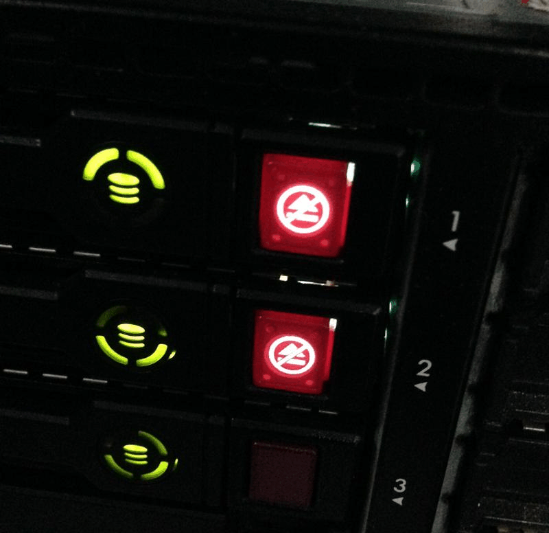
Figure 7-6 Disk Array Indicator Lights
7.1.3 Disk Array + Backup Drive
A RAID 10 array can tolerate up to 50% disk failures. However, an extreme scenario exists where all disks within the same RAID 10 array fail simultaneously, leading to data loss. In other words, within a RAID 10 array, if one disk in the RAID 1 subsystem fails and another disk in that same RAID 1 subsystem happens to fail while you're en route to repair the first one, the data is irretrievably lost.Instructor Liu Chuan certainly wasn't jinxing us—this exact scenario of simultaneous disk failures in a RAID 1 array has actually happened to one of my students.
What should be done in such a situation? Actually, RAID backup disk technology can completely prevent this type of accident. The core concept of this technology is to prepare a sufficiently large disk that remains idle under normal circumstances. Once a disk in the RAID array fails, this disk will immediately and automatically take its place. Pretty awesome, right?
To avoid conflicts between experiments, we must ensure each experiment operates independently. Therefore, everyone must restore their virtual machines to their initial state.Additionally, since we've already demonstrated deploying a RAID 10 array, let's now examine the deployment of a RAID 5 array. Deploying a RAID 5 array requires at least three disks plus one spare disk (also known as a hot spare). Therefore, a total of four disk devices must be simulated within the virtual machine, as shown in Figure 7-7.
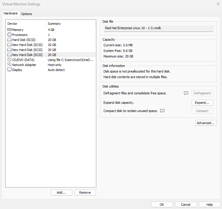
Figure 7-7: After resetting the virtual machine, add four hard disk devices
Now create a RAID 5 disk array with a spare disk. In the following command, the -n 3 parameter specifies the number of disks required for the RAID 5 array, -l 5 defines the RAID level, and -x 1 indicates one spare disk.When inspecting the /dev/md0 array (the RAID 5 array's name), you can see the spare disk is now waiting.
root@linuxprobe:~# mdadm -Cv /dev/md0 -n 3 -l 5 -x 1 /dev/sdb /dev/sdc /dev/sdd /dev/sde
mdadm: layout defaults to left-symmetric
mdadm: chunk size defaults to 512K
mdadm: size set to 20954112K
mdadm: Defaulting to version 1.2 metadata
mdadm: array /dev/md0 started.
root@linuxprobe:~# mdadm -D /dev/md0
/dev/md0:
           Version : 1.2
     Creation Time : Mon Mar 17 22:22:57 2025
        Raid Level : raid5
        Array Size : 41908224 (39.97 GiB 42.91 GB)
     Used Dev Size : 20954112 (19.98 GiB 21.46 GB)
      Raid Devices : 3
     Total Devices : 4
       Persistence : Superblock is persistent

       Update Time : Mon Mar 17 22:24:43 2025
             State : clean
    Active Devices : 3
   Working Devices : 4
    Failed Devices : 0
     Spare Devices : 1

            Layout : left-symmetric
        Chunk Size : 512K

Consistency Policy : resync

              Name : linuxprobe.com:0  (local to host linuxprobe.com)
              UUID : ae39f666:bae02cb8:45ba71d7:51223d5d
            Events : 18

    Number   Major   Minor   RaidDevice State
       0       8       16        0      active sync   /dev/sdb
       1       8       32        1      active sync   /dev/sdc
       4       8       48        2      active sync   /dev/sdd

       3       8       64        -      spare   /dev/sde
Now format the deployed RAID 5 disk array to the Ext4 file system, then mount it to a directory for use:
root@linuxprobe:~# mkfs.ext4 /dev/md0
mke2fs 1.47.1 (20-May-2024)
Creating filesystem with 10477056 4k blocks and 2621440 inodes
Filesystem UUID: 9c111651-c594-4458-96ec-364d27d28ec9
Superblock backups stored on blocks:
	32768, 98304, 163840, 229376, 294912, 819200, 884736, 1605632, 2654208,
	4096000, 7962624

Allocating group tables: done
Writing inode tables: done
Creating journal (65536 blocks): done
Writing superblocks and filesystem accounting information: done
root@linuxprobe:~# mkdir /RAID
root@linuxprobe:~# echo "/dev/md0 /RAID ext4 defaults 0 0" >> /etc/fstab
After modifying the /etc/fstab file on RHEL 10, automatic mounting via mount -a won't work immediately. You must first synchronize the changes to the system.
root@linuxprobe:~# systemctl daemon-reload
root@linuxprobe:~# mount -a
A RAID 5 array composed of three 20GB disks provides (n - 1) × disk capacity usable space, i.e., (3 - 1) × 20GB = 40GB. The hot spare disk's space is not included in this calculation; it remains inactive ("sleeping") and only activates during failures.
root@linuxprobe:~# df -h
Filesystem             Size  Used Avail Use% Mounted on
/dev/mapper/rhel-root   17G  3.7G   13G  23% /
devtmpfs               4.0M     0  4.0M   0% /dev
tmpfs                  1.9G   84K  1.9G   1% /dev/shm
efivarfs               256K   56K  196K  23% /sys/firmware/efi/efivars
tmpfs                  776M  9.7M  767M   2% /run
tmpfs                  1.0M     0  1.0M   0% /run/credentials/systemd-journald.service
/dev/sda2              960M  272M  689M  29% /boot
/dev/sr0               6.5G  6.5G     0 100% /media/cdrom
/dev/sda1              599M  8.3M  591M   2% /boot/efi
tmpfs                  388M  124K  388M   1% /run/user/0
/dev/md0                40G   24K   38G   1% /RAID
Finally, the moment of truth! We removed the disk device /dev/sdb from the RAID array once more and immediately checked
the status of the /dev/md0 RAID array. You'll see the spare disk has automatically taken its place and started data synchronization. This spare disk technology in RAID is incredibly practical, enhancing data reliability while ensuring the security of the RAID array. So, if your company isn't strapped for cash, it's worth investing in a spare disk just in case.
root@linuxprobe:~# mdadm /dev/md0 -f /dev/sdb
mdadm: set /dev/sdb faulty in /dev/md0
root@linuxprobe:~# mdadm -D /dev/md0
/dev/md0:
           Version : 1.2
     Creation Time : Mon Mar 17 22:22:57 2025
        Raid Level : raid5
        Array Size : 41908224 (39.97 GiB 42.91 GB)
     Used Dev Size : 20954112 (19.98 GiB 21.46 GB)
      Raid Devices : 3
     Total Devices : 4
       Persistence : Superblock is persistent

       Update Time : Mon Mar 17 22:32:18 2025
             State : clean
    Active Devices : 3
   Working Devices : 3
    Failed Devices : 1
     Spare Devices : 0

            Layout : left-symmetric
        Chunk Size : 512K

Consistency Policy : resync

              Name : linuxprobe.com:0  (local to host linuxprobe.com)
              UUID : ae39f666:bae02cb8:45ba71d7:51223d5d
            Events : 37

    Number   Major   Minor   RaidDevice State
       3       8       64        0      active sync   /dev/sde
       1       8       32        1      active sync   /dev/sdc
       4       8       48        2      active sync   /dev/sdd

       0       8       16        -      faulty   /dev/sdb
Pretty interesting, right? Due to space constraints, we haven't copied and pasted the files from the /RAID directory. Interested readers can try it themselves. The contents are perfectly safe and won't be lost. If you later want to add another hot spare disk, just use the -a parameter.
7.1.4 Removing a RAID Array
In production environments, RAID arrays are rarely decommissioned once deployed. However, knowing how to remove one remains essential. The scenario described earlier—a RAID 5 array with a failed hot spare—is complex, making it an ideal example for this explanation.
First, unmount and stop the RAID array:
root@linuxprobe:~# umount /dev/md0
umount: /dev/md0: not mounted.
root@linuxprobe:~# mdadm -S /dev/md0
mdadm: stopped /dev/md0
Since data remains on the member disks, a malicious hacker could potentially recover the data by rebuilding a RAID using these disks. To be safe, at least clear the RAID superblock on each original member disk so that it can no longer be automatically assembled into the old array:
root@linuxprobe:~# mdadm --zero-superblock /dev/sdb
root@linuxprobe:~# mdadm --zero-superblock /dev/sdc
root@linuxprobe:~# mdadm --zero-superblock /dev/sdd
root@linuxprobe:~# mdadm --zero-superblock /dev/sde
Afterward, no information related to the /dev/md0 device will be visible:
root@linuxprobe:~# mdadm -D /dev/md0
mdadm: cannot open /dev/md0: No such file or directory
root@linuxprobe:~# ls -l /dev/md0
ls: cannot access '/dev/md0': No such file or directory
Finally, remove the mount entry from the /etc/fstab file, and you're done!
root@linuxprobe:~# cat /etc/fstab
#
# /etc/fstab
# Created by anaconda on Wed Mar 12 19:35:26 2025
#
# Accessible filesystems, by reference, are maintained under '/dev/disk/'.
# See man pages fstab(5), findfs(8), mount(8) and/or blkid(8) for more info.
#
# After editing this file, run 'systemctl daemon-reload' to update systemd
# units generated from this file.
#
UUID=408f4a3d-a4d3-4a44-bb23-6988cdbd10bf /                     xfs     defaults        0 0
UUID=4cf8ecae-bcb6-4b1e-8001-968b33643a8a /boot                 xfs     defaults        0 0
UUID=1FB8-9199         			 		  /boot/efi             vfat    umask=0077,shortname=winnt 0 2
UUID=d936c726-45a7-4ca2-8932-c54f84a3d787 none                  swap    defaults        0 0
/dev/cdrom 								  /media/cdrom 			iso9660 defaults 		  0 0
7.2 LVM
While the disk device management techniques covered earlier effectively enhance disk I/O performance and data security, modifying partition sizes becomes challenging once disks are partitioned or deployed as RAID arrays.In other words, when users need to adjust partition sizes to accommodate changing requirements, they face limitations in disk "flexibility." This is where another widely adopted disk resource management technique comes into play—the Logical Volume Manager (LVM). LVM enables dynamic adjustment of disk resources.
LVM is a mechanism within Linux systems for managing disk partitions. It is a highly theoretical approach, originally designed to address the limitation that disk partitions are difficult to resize after creation. While forcibly expanding or shrinking traditional disk partitions is theoretically possible, it risks data loss.LVM technology introduces a logical layer between disk partitions and file systems. It provides an abstract volume group that can combine multiple disks into volumes. This allows users to dynamically adjust disk partitions without concerning themselves with the underlying architecture and layout of physical disk devices. The technical architecture of LVM is shown in Figure 7-8.
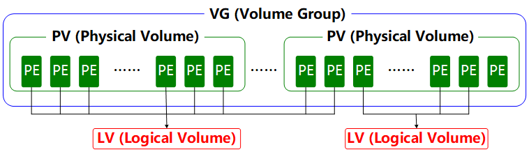
Figure 7-8 Technical Structure of the Logical Volume Manager
To aid understanding, consider an analogy involving a "foodie." Suppose Xiaoming's family wants to eat steamed buns but runs out of flour. His mother borrows some flour from neighbors Wang, Li, and Zhang to prepare the buns.First, she kneads all this flour (Physical Volumes, PVs) into one large dough ball (Volume Group, VG). Then she divides this dough into individual steamed buns (Logical Volumes, LVs), ensuring each bun's weight is a multiple of each scoop of flour (Physical Extents, PEs).
In daily use, if the Volume Group (VG) runs low on capacity, new Physical Volumes (PVs) can be added at any time to continuously expand it. To ensure clarity, a flowchart illustrating the Logical Volume Manager usage process is provided in Figure 7-9.
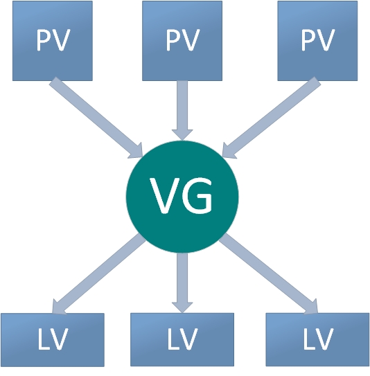
Figure 7-9: Logical Volume Manager Usage Flowchart
Physical volumes form the base layer of LVM and can be conceptualized as physical disks, disk partitions, or RAID disk arrays.Volume groups are built upon physical volumes. A single volume group can contain multiple physical volumes, and new physical volumes can be added to an existing volume group after its creation. Logical volumes are created using the free resources within a volume group. Once created, logical volumes can be dynamically expanded or shrunk. This is the core concept of LVM.
7.2.1 Deploying Logical Volumes
In production environments, it's often challenging to accurately predict the future usage requirements of each disk partition during initial setup. This frequently leads to situations where partition capacity becomes insufficient.For instance, as business volume increases, the database directory storing transaction records grows accordingly. Similarly, analyzing and logging user behavior causes log directories to expand continuously, leading to existing disk partitions becoming insufficient. Additionally, scenarios may arise where larger disk partitions need to be reduced in size.
We can address these issues by deploying LVM. During deployment, physical volumes, volume groups, and logical volumes must be configured individually. Common deployment commands are shown in Table 7-3.
Table 7-3 Common LVM Deployment Commands
| Function/Command | Physical Volume Management | Volume Group Management | Logical Volume Management |
|---|---|---|---|
| Scan | pvscan | vgscan | lvscan |
| Create | pvcreate | vgcreate | lvcreate |
| Display | pvdisplay | vgdisplay | lvdisplay |
| Delete | pvremove | vgremove | lvremove |
| Extend | vgextend | lvextend | |
| Shrink | vgreduce | lvreduce |
To avoid conflicts between experiments, please restore your virtual machine to its initial state and add two new disk devices as shown in Figure 7-10. Then power on the machine.
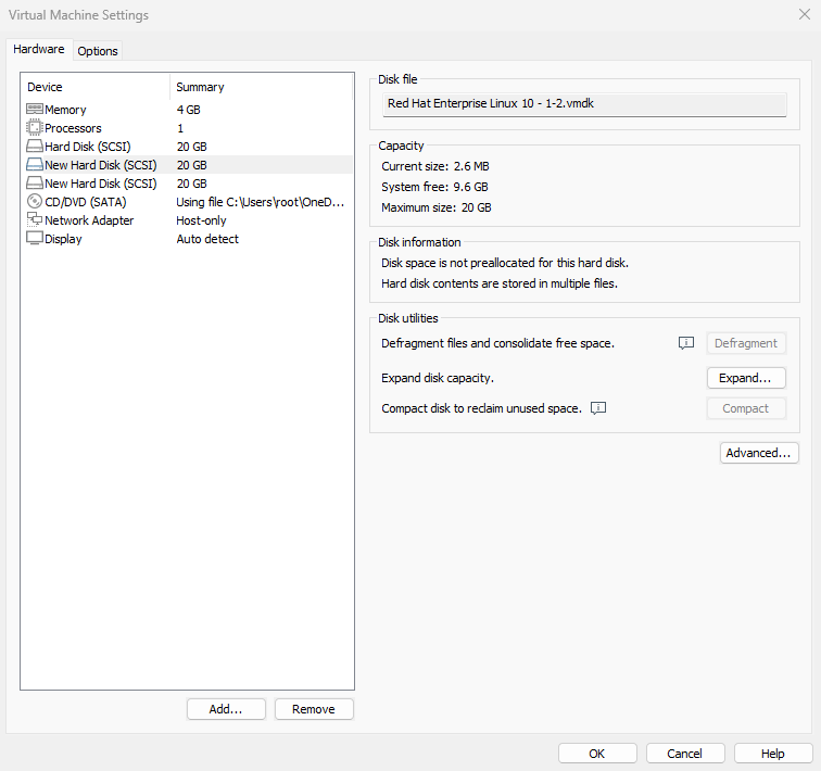
Figure 7-10 Adding two new hard disk devices in the virtual machine
Adding two new disk devices to the virtual machine better demonstrates the LVM concept that users need not concern themselves with the characteristics of underlying physical disk devices.First, we create physical volumes on these two new disks. This operation can be simply understood as enabling LVM support on the disk devices, or adding them to the hardware resource pool managed by LVM. Next, we combine these two disks into a volume group, whose name can be customized by the user.Next, based on requirements, we'll partition the combined volume group into a logical volume device of approximately 150MB. Finally, we'll format this logical volume device as an Ext4 filesystem and mount it for use. The following sections briefly describe each step.
Step 1: Enable LVM support on the two newly added disk devices.
root@linuxprobe:~# pvcreate /dev/sdb /dev/sdc
  Physical volume "/dev/sdb" successfully created.
  Physical volume "/dev/sdc" successfully created.
Step 2: Add both disk devices to the storage volume group, then check the volume group status.
root@linuxprobe:~# vgcreate storage /dev/sdb /dev/sdc
  Volume group "storage" successfully created
root@linuxprobe:~# vgdisplay
  --- Volume group ---
  VG Name               storage
  System ID
  Format                lvm2
  Metadata Areas        2
  Metadata Sequence No  1
  VG Access             read/write
  VG Status             resizable
  MAX LV                0
  Cur LV                0
  Open LV               0
  Max PV                0
  Cur PV                2
  Act PV                2
  VG Size               39.99 GiB
  PE Size               4.00 MiB
  Total PE              10238
  Alloc PE / Size       0 / 0
  Free  PE / Size       10238 / 39.99 GiB
  VG UUID               M9xB4b-sydm-G6tZ-K00e-RO45-iqL2-4bRlw1
[... output omitted ...]
Step 3: Create a logical volume device approximately 150MB in size.
Note the unit of measurement for partitioning. Two units are available when creating logical volumes: capacity-based (using the -L parameter) and number of basic units (using the -l parameter). Each basic unit defaults to 4MB.For example, using -l 37 creates a logical volume of 37 × 4MB = 148MB.
root@linuxprobe:~# lvcreate -n vo -l 37 storage
  Logical volume "vo" created.
root@linuxprobe:~# lvdisplay
  --- Logical volume ---
  LV Path                /dev/storage/vo
  LV Name                vo
  VG Name                storage
  LV UUID                9Tuv9a-FjmN-Cbye-CqC6-709V-zJMh-MQ9iIr
  LV Write Access        read/write
  LV Creation host, time linuxprobe.com, 2025-03-18 01:15:48 +0800
  LV Status              available
  # open                 0
  LV Size                148.00 MiB
  Current LE             37
  Segments               1
  Allocation             inherit
  Read ahead sectors     auto
  - currently set to     8192
  Block device           253:2
[... output omitted ...]
Step 4: Format the created logical volume and mount it for use.
Linux stores LVM logical volume devices in the /dev directory (essentially a shortcut), creating a directory named after the volume group. This directory contains the device mapping files for logical volumes (i.e., /dev/volume_group_name/logical_volume_name).
root@linuxprobe:~# mkfs.ext4 /dev/storage/vo
mke2fs 1.47.1 (20-May-2024)
Creating filesystem with 151552 1k blocks and 37848 inodes
Filesystem UUID: c5b6efaf-0b25-4ad2-81ac-afb8bc0c99a9
Superblock backups stored on blocks:
	8193, 24577, 40961, 57345, 73729

Allocating group tables: done
Writing inode tables: done
Creating journal (4096 blocks): done
Writing superblocks and filesystem accounting information: done

root@linuxprobe:~# mkdir /linuxprobe
root@linuxprobe:~# mount /dev/storage/vo /linuxprobe
By the way, although many distributions use XFS on top of LVM by default, we've run into a few edge cases where this combination behaved poorly on certain servers. For the purposes of this book, we recommend using Ext4 with LVM to keep the examples simple and predictable.
Step 5: Verify the mount status and write to the configuration file to make the changes permanent.
root@linuxprobe:~# df -h
Filesystem              Size  Used Avail Use% Mounted on
/dev/mapper/rhel-root    17G  3.7G   13G  23% /
devtmpfs                4.0M     0  4.0M   0% /dev
tmpfs                   1.9G   84K  1.9G   1% /dev/shm
efivarfs                256K   56K  196K  23% /sys/firmware/efi/efivars
tmpfs                   776M  9.7M  767M   2% /run
tmpfs                   1.0M     0  1.0M   0% /run/credentials/systemd-journald.service
/dev/sda2               960M  272M  689M  29% /boot
/dev/sr0                6.5G  6.5G     0 100% /media/cdrom
/dev/sda1               599M  8.3M  591M   2% /boot/efi
tmpfs                   388M  124K  388M   1% /run/user/0
/dev/mapper/storage-vo  134M   14K  123M   1% /linuxprobe
root@linuxprobe:~# echo "/dev/storage/vo /linuxprobe ext4 defaults 0 0" >> /etc/fstab
root@linuxprobe:~# cat /etc/fstab
#
# /etc/fstab
# Created by anaconda on Wed Mar 12 19:35:26 2025
#
# Accessible filesystems, by reference, are maintained under '/dev/disk/'.
# See man pages fstab(5), findfs(8), mount(8) and/or blkid(8) for more info.
#
# After editing this file, run 'systemctl daemon-reload' to update systemd
# units generated from this file.
#
UUID=408f4a3d-a4d3-4a44-bb23-6988cdbd10bf /                       xfs     defaults        0 0
UUID=4cf8ecae-bcb6-4b1e-8001-968b33643a8a /boot                   xfs     defaults        0 0
UUID=1FB8-9199          /boot/efi                      vfat    umask=0077,shortname=winnt 0 2
UUID=d936c726-45a7-4ca2-8932-c54f84a3d787 none                    swap    defaults        0 0
/dev/cdrom 								  /media/cdrom 			iso9660   defaults		  0 0
/dev/storage/vo 						  /linuxprobe 			  ext4    defaults 		  0 0
Tips:
Observant students may have noticed another small discrepancy: Earlier it clearly stated 148MB, so why is it only 140MB here? This discrepancy arises because hardware manufacturers use the standard conversion: 1GB = 1000MB, 1MB = 1000KB, 1KB = 1000B. However, computer systems recognize and calculate storage capacity using binary arithmetic, where 1GB = 1024MB,
1MB = 1024KB, 1KB = 1024B. Therefore, a roughly 3% discrepancy is normal.
7.2.2 Expanding a Logical Volume
In previous experiments, the volume group was composed of two disk devices. Users remain unaware of the underlying architecture and layout of storage devices, nor do they need to concern themselves with the number of disks within the volume group. As long as sufficient resources exist within the volume group, logical volumes can be expanded continuously. Before expanding, always remember to unmount the device from its mount point.
root@linuxprobe:~# umount /linuxprobe
Step 1: Extend the logical volume vo from the previous experiment to 290MB.
root@linuxprobe:~# lvextend -L 290M /dev/storage/vo
  Rounding size to boundary between physical extents: 292.00 MiB.
  Size of logical volume storage/vo changed from 148.00 MiB (37 extents) to 292.00 MiB (73 extents).
  Logical volume storage/vo successfully resized.
Step 2: Verify disk integrity to ensure no loss of directory structure, content, or file data. Generally, no errors indicate successful operation.
root@linuxprobe:~# e2fsck -f /dev/storage/vo
e2fsck 1.47.1 (20-May-2024)
Pass 1: Checking inodes, blocks, and sizes
Pass 2: Checking directory structure
Pass 3: Checking directory connectivity
Pass 4: Checking reference counts
Pass 5: Checking group summary information
/dev/storage/vo: 11/37848 files (0.0% non-contiguous), 15165/151552 blocks
Step 3: Reset the device's capacity in the system. The LV (Logical Volume) device was just expanded, but the system kernel has not yet synchronized this new modification. Manual synchronization is required.
root@linuxprobe:~# resize2fs /dev/storage/vo
resize2fs 1.47.1 (20-May-2024)
Resizing the filesystem on /dev/storage/vo to 299008 (1k) blocks.
The filesystem on /dev/storage/vo is now 299008 (1k) blocks long.
Step 4: Remount the disk device and check the mount status.
root@linuxprobe:~# systemctl daemon-reload
root@linuxprobe:~# mount -a
root@linuxprobe:~# df -h
Filesystem              Size  Used Avail Use% Mounted on
/dev/mapper/rhel-root    17G  3.7G   13G  23% /
devtmpfs                4.0M     0  4.0M   0% /dev
tmpfs                   1.9G   84K  1.9G   1% /dev/shm
efivarfs                256K   56K  196K  23% /sys/firmware/efi/efivars
tmpfs                   776M  9.7M  767M   2% /run
tmpfs                   1.0M     0  1.0M   0% /run/credentials/systemd-journald.service
/dev/sda2               960M  272M  689M  29% /boot
/dev/sr0                6.5G  6.5G     0 100% /media/cdrom
/dev/sda1               599M  8.3M  591M   2% /boot/efi
tmpfs                   388M  124K  388M   1% /run/user/0
/dev/mapper/storage-vo  268M   14K  250M   1% /linuxprobe
7.2.3 Shrinking a Logical Volume
Compared to expanding a logical volume, shrinking one carries a higher risk of data loss. Therefore, always back up your data before performing this operation in a production environment.Additionally, Linux systems require verifying the filesystem integrity before shrinking an LVM logical volume (this also ensures data safety). Remember to unmount the filesystem before shrinking.
root@linuxprobe:~# umount /linuxprobe
Step 1: Verify filesystem integrity.
root@linuxprobe:~# e2fsck -f /dev/storage/vo
e2fsck 1.47.1 (20-May-2024)
Pass 1: Checking inodes, blocks, and sizes
Pass 2: Checking directory structure
Pass 3: Checking directory connectivity
Pass 4: Checking reference counts
Pass 5: Checking group summary information
/dev/storage/vo: 11/73704 files (0.0% non-contiguous), 24683/299008 blocks
Step 2: Notify the system kernel to reduce the capacity of the logical volume vo to 120MB.
root@linuxprobe:~# resize2fs /dev/storage/vo 120M
resize2fs 1.47.1 (20-May-2024)
Resizing the filesystem on /dev/storage/vo to 122880 (1k) blocks.
The filesystem on /dev/storage/vo is now 122880 (1k) blocks long.
Huh? The steps for shrinking are different from expanding. Why does shrinking first notify the kernel that the device capacity should change to 120MB before performing the actual shrink operation? An example will make it clear.Xiao Qiang is a middle school student. After school started, he noticed a classmate with a tattoo and thought it looked cool. He wanted one too but feared his parents' scolding. So he went home and said, "Mom, I got a tattoo." If his mom reacted calmly, he could go get one without worry. If she strongly disagreed, he'd immediately laugh and say, "Just kidding!" That way, he wouldn't get punished.
Resizing works the same way. First, notify the system kernel that you want to shrink the logical volume. If the system reports no errors after executing the resize2fs command, proceed with the actual operation.
Step 3: Reduce the LV logical volume capacity to 120MB.
root@linuxprobe:~# lvreduce -L 120M /dev/storage/vo
  File system ext4 found on storage/vo.
  File system size (120.00 MiB) is equal to the requested size (120.00 MiB).
  File system reduce is not needed, skipping.
  Size of logical volume storage/vo changed from 292.00 MiB (73 extents) to 120.00 MiB (30 extents).
  Logical volume storage/vo successfully resized.
When formally shrinking a file system using the lvreduce command, the size must exactly match the previously declared value. If you specified 120MB, even a 1MB, 1KB, or 1B discrepancy is unacceptable. Imagine Xiao Ming finally persuading his mom to let him get a kitten tattoo, only to end up with a mountain tiger instead—he'd still get a beating (resize failure).
Step 4: Remount the filesystem and check the system status.
root@linuxprobe:~# mount -a
root@linuxprobe:~# df -h
Filesystem              Size  Used Avail Use% Mounted on
/dev/mapper/rhel-root    17G  3.7G   13G  23% /
devtmpfs                4.0M     0  4.0M   0% /dev
tmpfs                   1.9G   84K  1.9G   1% /dev/shm
efivarfs                256K   56K  196K  23% /sys/firmware/efi/efivars
tmpfs                   776M  9.7M  767M   2% /run
tmpfs                   1.0M     0  1.0M   0% /run/credentials/systemd-journald.service
/dev/sda2               960M  272M  689M  29% /boot
/dev/sr0                6.5G  6.5G     0 100% /media/cdrom
/dev/sda1               599M  8.3M  591M   2% /boot/efi
tmpfs                   388M  124K  388M   1% /run/user/0
/dev/mapper/storage-vo  108M   14K   99M   1% /linuxprobe
7.2.4 Logical Volume Snapshots
LVM also provides "logical volume snapshots," a feature analogous to the restore point functionality in virtual machine software. For example, taking a snapshot of a logical volume allows you to revert to that state if data is later altered incorrectly. LVM's logical volume snapshot feature has two key behaviors that matter for our experiments:
-
In this book, we create snapshots with the same capacity as the original logical volume to ensure there is enough copy-on-write space. In real environments you can often allocate a smaller snapshot if you know roughly how much data will change.
-
When you use
lvconvert --mergeto roll back from a snapshot, the snapshot logical volume is automatically deleted after the merge—you cannot reuse that same snapshot again.
Before proceeding, verify sufficient capacity within the VG (Volume Group):
root@linuxprobe:~# vgdisplay
  --- Volume group ---
  VG Name               storage
  System ID
  Format                lvm2
  Metadata Areas        2
  Metadata Sequence No  4
  VG Access             read/write
  VG Status             resizable
  MAX LV                0
  Cur LV                1
  Open LV               1
  Max PV                0
  Cur PV                2
  Act PV                2
  VG Size               39.99 GiB
  PE Size               4.00 MiB
  Total PE              10238
  Alloc PE / Size       30 / 120.00 MiB
  Free  PE / Size       10208 / <39.88 GiB
  VG UUID               M9xB4b-sydm-G6tZ-K00e-RO45-iqL2-4bRlw1
[... output omitted ...]
The volume group output clearly shows that 120MB of capacity has been used, with 39.88GB of free space remaining. Next, write a file to the directory mounted on the logical volume device using redirection.
root@linuxprobe:~# echo "Welcome to Linuxprobe.com" > /linuxprobe/readme.txt
root@linuxprobe:~# ls -l /linuxprobe
total 13
drwx------. 2 root root 12288 Mar 18 01:16 lost+found
-rw-r--r--. 1 root root    26 Mar 18 01:43 readme.txt
Step 1: Generate a logical volume snapshot using the -s parameter. Specify the partition size with the -L parameter, which must match the capacity of the device to be snapped. Additionally, include the logical volume name after the command to indicate which volume the snapshot operation targets. Data will later be restored to this corresponding device.
root@linuxprobe:~# lvcreate -L 120M -s -n SNAP /dev/storage/vo
 Logical volume "SNAP" created.
root@linuxprobe:~# lvdisplay
  --- Logical volume ---
  LV Path                /dev/storage/SNAP
  LV Name                SNAP
  VG Name                storage
  LV UUID                XsCyvN-NiXP-M6tD-CfXk-TCQU-PSbQ-eYHaV2
  LV Write Access        read/write
  LV Creation host, time linuxprobe.com, 2025-03-18 01:43:57 +0800
  LV snapshot status     active destination for vo
  LV Status              available
  # open                 0
  LV Size                120.00 MiB
  Current LE             30
  COW-table size         120.00 MiB
  COW-table LE           30
  Allocated to snapshot  0.01%
  Snapshot chunk size    4.00 KiB
  Segments               1
  Allocation             inherit
  Read ahead sectors     auto
  - currently set to     256
  Block device           253:5
[... output omitted ...]
Step 2: Create a 100MB dummy file in the directory where the logical volume is mounted, then check the snapshot status again. You'll notice the storage space usage has increased.
root@linuxprobe:~# dd if=/dev/zero of=/linuxprobe/files count=1 bs=100M
1+0 records in
1+0 records out
104857600 bytes (105 MB, 100 MiB) copied, 0.461243 s, 227 MB/s
root@linuxprobe:~# lvdisplay
  --- Logical volume ---
  LV Path                /dev/storage/SNAP
  LV Name                SNAP
  VG Name                storage
  LV UUID                XsCyvN-NiXP-M6tD-CfXk-TCQU-PSbQ-eYHaV2
  LV Write Access        read/write
  LV Creation host, time linuxprobe.com, 2025-03-18 01:43:57 +0800
  LV snapshot status     active destination for vo
  LV Status              available
  # open                 0
  LV Size                120.00 MiB
  Current LE             30
  COW-table size         120.00 MiB
  COW-table LE           30
  Allocated to snapshot  67.28%
  Snapshot chunk size    4.00 KiB
  Segments               1
  Allocation             inherit
  Read ahead sectors     auto
  - currently set to     256
  Block device           253:5
[... output omitted ...]
Step 3: To verify the effectiveness of the logical volume snapshot, perform a snapshot restore operation on the logical volume. Before proceeding, remember to unmount the logical volume device and directory.
The lvconvert command manages logical volume snapshots with the syntax lvconvert [options] logical_volume_snapshot_name. This command automatically restores the logical volume snapshot. In earlier RHEL/CentOS 5 versions, the full command --mergesnapshot was required. Starting from RHEL 6 through RHEL 10, users can simply enter --mergesnapshot. format: --mergesnapshot. However, starting from RHEL 6 through RHEL 10, users can now simply input --merge parameter for the operation, with the system automatically identifying the device type.
root@linuxprobe:~# umount /linuxprobe
root@linuxprobe:~# lvconvert --merge /dev/storage/SNAP
  Merging of volume storage/SNAP started.
  storage/vo: Merged: 100.00%
Step 4: The logical volume snapshot is automatically deleted, and the 100MB temporary file created during the snapshot operation is also cleared.
root@linuxprobe:~# mount -a
root@linuxprobe:~# cd /linuxprobe
root@linuxprobe:/linuxprobe# ls
lost+found  readme.txt
root@linuxprobe:/linuxprobe# cat readme.txt
Welcome to Linuxprobe.com
7.2.5 Deleting Logical Volumes
When redeploying LVM in a production environment or no longer requiring LVM, perform the deletion operation. First, back up critical data. Then sequentially delete logical volumes, volume groups, and physical volumes—this order must not be reversed.
Step 1: Unmount the logical volume from its directory and remove the permanent device parameters from the configuration file.
root@linuxprobe:/linuxprobe# cd ~
root@linuxprobe:~# umount /linuxprobe
root@linuxprobe:~# vim /etc/fstab
#
# /etc/fstab
# Created by anaconda on Tue Jul 21 05:03:40 2020
#
# Accessible filesystems, by reference, are maintained under '/dev/disk/'.
# See man pages fstab(5), findfs(8), mount(8) and/or blkid(8) for more info.
#
# After editing this file, run 'systemctl daemon-reload' to update systemd
# units generated from this file.
#
/dev/mapper/rhel-root                       /                       xfs      defaults        0 0
UUID=2db66eb4-d9c1-4522-8fab-ac074cd3ea0b   /boot                   xfs      defaults        0 0
/dev/mapper/rhel-swap                       swap                    swap     defaults        0 0
/dev/cdrom                                  /media/cdrom            iso9660  defaults        0 0
Step 2: Remove the logical volume device. You must enter y to confirm the operation.
root@linuxprobe:~# lvremove /dev/storage/vo
Do you really want to remove active logical volume storage/vo? [y/n]: y
  Logical volume "vo" successfully removed.
Step 3: Remove the volume group. Only the volume group name is required here; the absolute device path is unnecessary.
root@linuxprobe:~# vgremove storage
  Volume group "storage" successfully removed
Step 4: Remove the physical volume device.
root@linuxprobe:~# pvremove /dev/sdb /dev/sdc
  Labels on physical volume "/dev/sdb" successfully wiped.
  Labels on physical volume "/dev/sdc" successfully wiped.
After completing the above operations, running lvdisplay, vgdisplay, and pvdisplay commands to view LVM information will no longer show related details (assuming the steps were executed correctly). Clean and tidy!
Review Questions
- What problem does RAID technology primarily address?
Answer: RAID technology primarily addresses storage device I/O rate issues and provides redundant data backup.
- Which is more secure: RAID 0 or RAID 5?
Answer: RAID 0 lacks data redundancy, so RAID 5 is more secure.
- In a RAID 10 setup consisting of four data disks plus one hot spare(five disks in total), how many disks can fail without data loss?
Answer: Up to 3 disks can fail in sequence under ideal conditions, as long as the hot spare has finished rebuilding and each mirror set always keeps at least one healthy disk. In the most favorable case, up to 3 out of the 5 disk devices can even fail simultaneously without data loss.
- Is a RAID 0 configuration with a hot spare disk feasible?
Answer: Absolutely not. In RAID 0, data is permanently lost upon failure of any data disk, with no recovery possible.
- Is the lowest layer of LVM a physical volume or a volume group?
Answer: The lowest level consists of physical volumes, which are then organized into volume groups.
- What are the similarities and differences between expanding and shrinking logical volumes in LVM?
Answer: Both operations require unmounting the logical volume from its directory. For expansion, the volume is enlarged first, followed by a filesystem integrity check. For contraction, to ensure data safety, the filesystem integrity check must be performed before shrinking the volume.
- How many times can an LVM logical volume snapshot be used?
Answer: Only once, and it is automatically deleted after use.
- What is the deletion sequence for LVM?
Answer: Logical volumes, volume groups, and physical volumes are removed in that order.
- Does LVM provide redundant backup functionality since it uses multiple disks?
Answer: Not only does it lack redundancy, but failure of any underlying disk will result in data loss.
- Can RAID and LVM be used together?
Answer: If required, this is possible. However, remember to create the RAID first, then build the LVM on top of it.